光貿易株式会社
〒113-0034
東京都文京区湯島3-13-8
湯島不二ビル301
電話番号:03-3832-3117
FAX番号 :03-3832-3118
MICRAM社
■メーカーの紹介 |
 |
|
|||||||||||||||
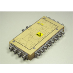
| ■製品概要/Product Overview | |
| The CDR14112 is a Ultrahigh-Speed CDR with integrated 1:4 Demultiplexer for data rates of 112 Gb/s and above. Key features are: - single-ended and differential IO operation, - broadband operation, - clock and clock/2 outputs available, - adjustable output swing, - single supply voltage, - integrated VCO and PLL (only external capacitance needed) |
|
PDFファイル:233 kb |
|
| ■特徴/Key Features |
| The CDR 14112 is a clock and data recovery circuitry with integrated 1:4 DEMUX, VCO and the opportunity to drive the module with an external clock signal. It is designed to fit for 107 to 112 Gb/s signal systems. The input amplifier is optimized for high input sensitivity (30mVpp min. input voltage swing) The module can selectively be used with an external clock signal or the internal VCO. To choose between both possibilities a clock selector is included. The default setting is the internal VCO drive. If an external clock is fed to the CDR the module can also be used at other data rates. With the up/down information controls and the external clock signal a PLL can be realized. The module has two clock outputs. One output provides the clock signal and the other output the half rated clock signal. The half rate clock output may be used for ongoing demultiplexing or for drive of following frequency dividers to generate a signal to synchronize other modules or measurement equipments. The CDR includes the possibility to shift the phase of the clock signal at the clock output to align for the phase of the data output. A monitor output is included for the observation of the performance of the amplified input data signal. |
| ■アプリケーション/Application |
| 107 to 112 Gb/s signal systems |